
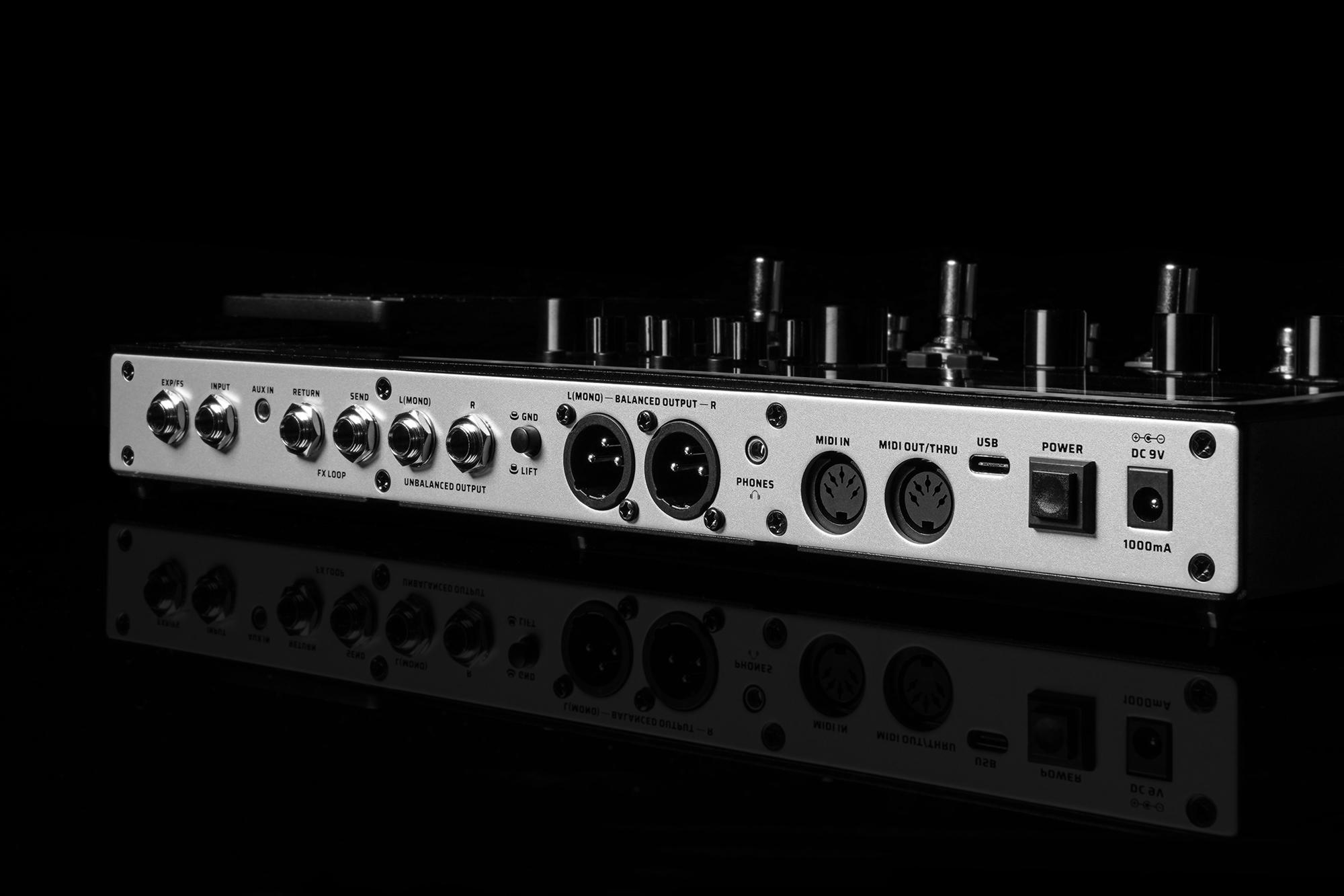
Recently while working on my midi bass project, I thought, “hey, I have a multi-effect pedal which has both unbalanced and balanced outputs, I wonder if I can reverse engineer that circuit and copy it for my own.” So I got started taking apart my Valeton GP-200, and had some fun learnings.
The Teardown
Taking apart the Valeton GP-200 is not hard. First, remove the 5 machine screws on the front o fthe unit. There are also 8 short machine screws on the back, 4 self-tapping screws for the XLR balanced jacks, and 6 nuts holding the TRS jacks in place. Once you remove those, the back panel can swing free, but be careful. The power switch has a short connector going from the button back to a PCB, which is hard to disconnect while the rest of the unit is put together. From the bottom, you will need to remove the 4 corner feet (you can leave the middle two feet attached), a longer machine screw in the middle of two corners, and 2 more machine screws in a line underneath the expression pedal. Once you remove those, the bottom panel can be removed, revealing the PCBs mounted to the top panel.
The Microcontroller
Once you remove the bottom panel, there is a small aluminum heatspreader that catches your eye. By removing the two machine screws keeping that in place, you can remove a daughter-board which houses the brain of this unit, the MIMXRT106FDVL6B. This little microcontroller houses a single Arm Cortex M7 core clocked at 600MHz, 1MB of onboard flash, and some multimedia features useful for driving the LCD on this unit. Interestingly enough, I chose a similar CPU (STM32H750) to drive my midi-synth project.
On the other side of the daughter board is a 256MB SDRAM chip which I’m guessing is needed for holding the effects chain models during processing, but I’m no expert in DSP.
Other Circuitry of Note
Obviously with basic tools I’m not going to be able to reverse engineer the circuits, however, I did find it interesting to note which components were being used, and based on logical groupings on the PCB, it made sense which components were paired with which circuits.
The first Circuit I was able to identify was the MIDI input circuit. The Midi inputs are right next to the Microcontroller, but there’s a little unmarked IC with 6 legs, which I believe is an optocoupler. This is required for proper MIDI input functionality to isolate incoming voltage from the rest of the operational voltage. There are also two diodes, which are part of basic midi circuits. There isn’t anything to special or noteworthy about this circuit, and a quick google of “MIDI Input Circuit” will give you a similar result design.
The board also uses a lot of 8-bit shift registers. Interestingly, there are different shift registers, even though they are all 8-bit shift registers, likely for combining the various digital inputs from the MFX unit. While one side of the board is packed with capacitors, OP Amps and ports, the other has a bunch of shift registers near where the rotary encoders, and breakout boards for the foot switches attach.
As an example, there were several ICs around the board with the marking “SGM 82702XS8 N2EKC” which are OP Amps.
https://www.nxp.com/part/MIMXRT106FDVL6B#/


Future Steps
I hope to be able to look into this interesting hardware more, however it’s been a long time since I last wrote. It looks like I need to figure out how to publish articles more regularly before I can take more time for longer projects like this.